teb_local_planner is one of the local planners (controllers) available in the ROS Navigation Stack and Nav2. Compared to DWA (Dynamic Window Approach), it can generate more complex avoidance trajectories but is characterized by relatively high computational cost. To achieve the intended behavior while suppressing computational cost, it is necessary to understand the algorithm and adjust its parameters. Therefore, this article aims to provide an overview of the teb_local_planner algorithm and enable users to perform parameter tuning.
Overview of Navigation and the Role of teb_local_planner
When a goal is given to the navigation module, movement to the goal is achieved by repeating the following flow:
Observation and estimation of self-position and obstacles.
Path planning (calculating the optimal sequence of Poses to the goal. In simple cases, this is done once each time a goal is given).
Trajectory planning (calculating the optimal Pose for each time instant until the goal).
Velocity and angular velocity control (calculating target velocity and angular velocity).
teb_local_planner handles trajectory planning and velocity/angular velocity control.
What is Timed Elastic Band (TEB)?
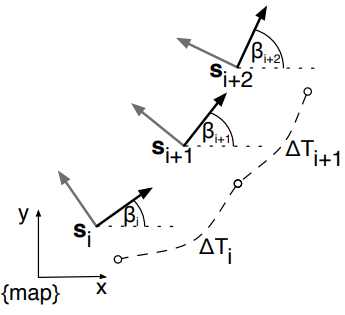
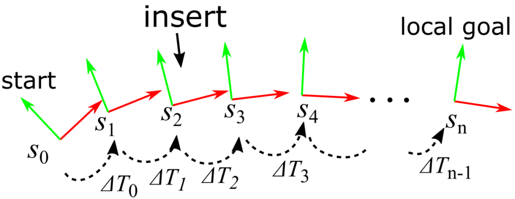
Timed Elastic Band is a model that represents a trajectory as “a sequence of Poses (position and orientation) and a sequence of travel times between Poses.” If the time taken to move from the i-th Pose \(s_i(x_i, y_i, \beta_i)\) to the (i+1)-th Pose \(s_{i+1}(x_{i+1}, y_{i+1}, \beta_{i+1})\) is \(\Delta T_i\), the concept is as follows:
teb_local_planner calculates the optimal trajectory to satisfy the following constraints and objective functions:
Velocity constraints (two consecutive Poses and the travel time between Poses)
Acceleration constraints (three consecutive Poses and the travel times between two Poses)
Obstacles/waypoints (Poses near obstacles/waypoints (k=3~5 Poses))
Non-holonomic constraints (two consecutive Poses)
Minimum time
Minimum distance
Constraints and objective functions defined by the relationship between adjacent Poses can be represented by a sparse matrix (a matrix where most of the components are zero), allowing for efficient calculation using a sparse matrix optimization library. (* Other constraints are introduced in the teb_local_planner implementation but are omitted here.)
Sparse Matrix Optimization
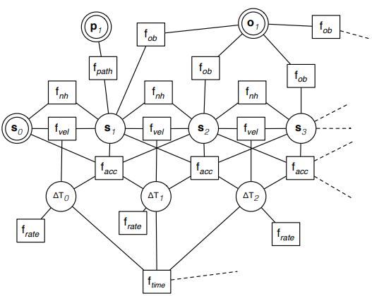
The above constraints and objective functions are represented by a Hyper-Graph (a graph where edges can connect multiple nodes) and optimized using g2o.
In the figure above, ‘s’ represents a Pose, ‘p’ a waypoint, ‘o’ an obstacle, and ΔT a node for the travel time between Poses. By connecting these nodes with edges representing constraints and objective functions, the optimization target is expressed as a graph.
Auto Resizing
After optimizing the Timed Elastic Band, the sampling interval may become inappropriate. Examples include:
The path is optimized to avoid obstacles, and sampling becomes coarse.
The goal is approaching, and sampling becomes excessively fine.
Coarse sampling reduces the trajectory’s representation capability, while excessively fine sampling increases computational cost. Auto resizing resolves this issue by inserting or deleting Poses and the travel times between Poses. The processing flow for when sampling becomes coarse is illustrated below.
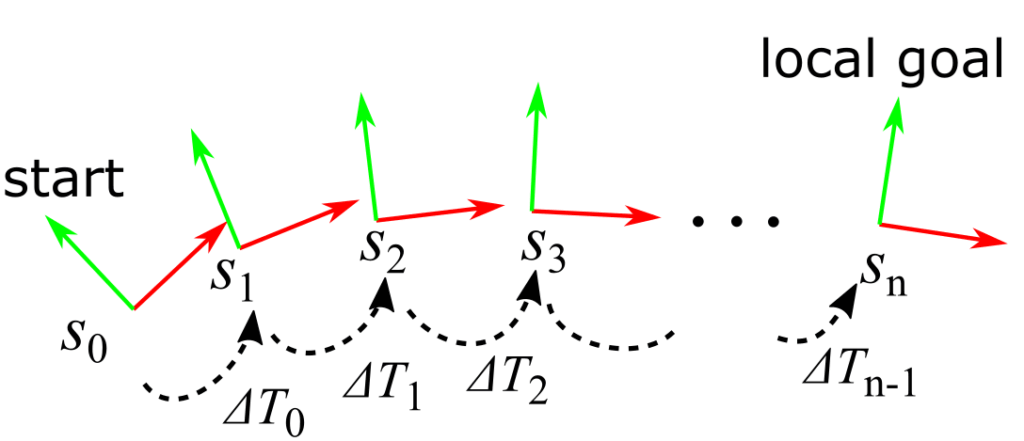
Before OptimizationBefore optimization, Poses are sampled at nearly equal intervals.
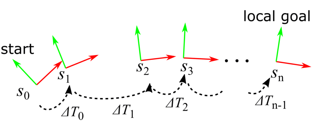
After OptimizationAfter optimization, the sampling interval may become coarse.
After Auto Resizing Auto resizing adjusts the sampling interval by inserting Poses and travel times between Poses.
TEB Optimization Process Flow
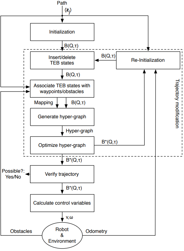
Each time a velocity/angular velocity calculation is requested from ROS Navigation Stack or Nav2, by default, the following flow is repeated 4 times:
Since TEB deforms trajectories continuously, deformations that cross over obstacles do not occur. Therefore, HomotopyClassPlanner is used to handle multiple trajectories.
What is a Homotopy Class?
Definition 1-1 (Homotopy): Two trajectories connecting the same start and end points are homotopic if and only if one can be continuously deformed into the other without intersecting obstacles.
Definition 1-2 (Homotopy classes): The set of all trajectories that are homotopic to each other is called a Homotopy class.
When handling multiple trajectories, one trajectory per Homotopy class is sufficient, so Homotopy class determination is performed for filtering.
H-signature for Homotopy Class Determination
An invariant quantity for a trajectory \(\tau\) belonging to a Homology class is defined as follows:
Here, \(\xi_{k}\) is a representative point of an obstacle.
By numerically calculating this invariant H-signature (for discrete trajectories), it is possible to determine whether two trajectories belong to the same Homology class by comparing their H-signatures. (The absolute difference for the real and imaginary parts is calculated respectively, and if it is smaller than a threshold, they belong to the same Homotopy class.)
Overview of the Process from Initial Trajectory Generation to Optimization
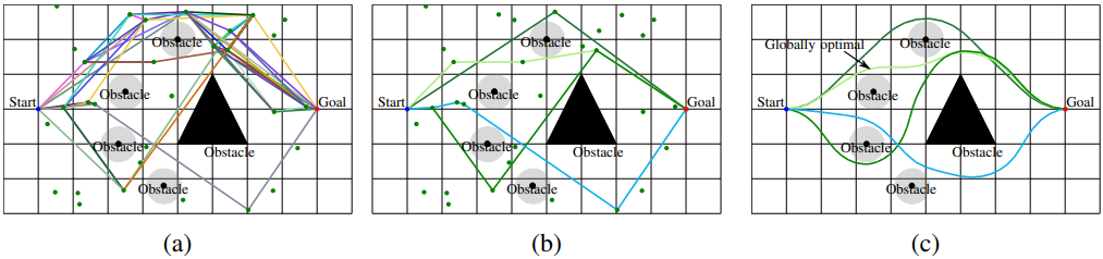
From the starting vertex, create edges that approach the goal and whose line segments do not intersect obstacles. Furthermore, repeat the process of creating edges from vertices connected to the starting vertex by edges, such that they approach the goal and their line segments do not intersect obstacles (Fig (a)).
For each path from start to goal, calculate the H-signature. If it’s a new Homotopy class, save the trajectory and H-signature (Fig (b)).
Optimize each trajectory with TEB (Fig (c)).
About Key Parameters
This section explains parameters that affect computational cost and parameters that require attention. (Unless otherwise noted, descriptions are based on the ROS2 version 0.9.1 (commit ID 630a22e)).
Costmap Related
footprint_model/type (string, default: “point”)
You can specify point, circle, line, two_circles, or polygon. Using polygon, in particular, increases computational cost.
exact_arc_length (bool, default: false)
If true, arc length is used instead of straight-line distance for calculating velocity and acceleration constraints.
costmap_converter_plugin (string, default: “”)
Specifies a plugin for converting the costmap to polygons, etc. By default, the costmap is used as is, but converting it to polygons may potentially reduce computational cost.
costmap_converter_rate (double, default: 5.0)
Specifies the frequency at which the costmap is converted to polygons by costmap_converter.
TEB, Auto Resizing Related
dt_ref (double, default: 0.3)
Specifies the time resolution. During auto resizing, the travel time between Poses is adjusted to approach this time.
dt_hysteresis (double, default: 0.1)
If the travel time between Poses falls outside the range of dt_ref +/- dt_hysteresis, Pose insertion/deletion by auto resizing is performed.
When initializing TEB, an initial Pose sequence is generated from start to goal. If this parameter is true, it allows the robot to move backward if the goal is behind the robot.
feasibility_check_no_poses (int, default: 5)
Since the optimal solution might result in a trajectory that collides with obstacles, collision checking is performed. This specifies how many Poses to check. A negative value checks all Poses.
Introduced in noetic/galactic and later because feasibility_check_no_poses might not fit within the local costmap range, among other reasons. If a non-negative value is specified, it takes precedence over feasibility_check_no_poses, and collision checking is performed up to the specified distance.
Treats points obtained by dividing the global plan at specified intervals as via-points. A negative value disables setting via-points this way.
viapoints_all_candidates (bool, default: true)
If true, via-points are considered for all candidate trajectories. If false, via-points are considered only for trajectories belonging to the same Homotopy class as the global plan.
weight_viapoint (double, default: 1.0)
Specifies the weight of the constraint for passing through via-points.
HomotopyClassPlanner Related
enable_multithreading (bool, default: true)
If true, one thread is allocated per trajectory for TEB optimization.
simple_exploration (bool, default: false)
If true, sampling is performed only to the left and right of obstacles, rather than Probabilistic Roadmap-like sampling.
roadmap_graph_no_samples (int, default: 15)
Specifies the number of samples. (Only if simple_exploration is false)
roadmap_graph_area_width (double, default: 5.0)
Specifies the sampling range.
max_number_classes (int, default: 4)
Specifies the upper limit of trajectories to handle.
The global plan is cropped up to this length and treated as the initial trajectory. However, if the trajectory goes outside 85% of the local costmap size, that part is treated as the initial trajectory. The end point becomes the local goal.
Overwrites the orientation of the local goal’s end point with an angle along the trajectory. This should be true if the global planner sets the orientation only for the goal.
no_outer_iterations (int, default: 4)
Specifies the number of times auto resizing is applied.
no_inner_iterations (int, default: 5)
Specifies the number of iterations for g2o’s OptimizationAlgorithmLevenberg per auto resizing pass.
About the Control Cycle
The frequency of requesting velocity and angular velocity calculations can be changed by the navigation module’s controller_frequency.
It cannot be prohibited by teb_local_planner settings, but setting weight_kinematics_forward_drive to a large value will almost prevent backward motion. (Reference: https://github.com/rst-tu-dortmund/teb_local_planner/issues/85) (Furthermore, it can be ensured by adding post-processing to change backward motion to a stop.)
References
The teb_local_planner README.md lists the following five, but for TEB in particular, “Efficient trajectory optimization using a sparse model.” was referenced, and for Homotopy class planning, “Planning of Multiple Robot Trajectories in Distinctive Topologies” was referenced.
C. Rösmann, F. Hoffmann and T. Bertram: Integrated online trajectory planning and optimization in distinctive topologies, Robotics and Autonomous Systems, Vol. 88, 2017, pp. 142–153.
C. Rösmann, W. Feiten, T. Wösch, F. Hoffmann and T. Bertram: Trajectory modification considering dynamic constraints of autonomous robots. Proc. 7th German Conference on Robotics, Germany, Munich, May 2012, pp 74–79.
C. Rösmann, W. Feiten, T. Wösch, F. Hoffmann and T. Bertram: Efficient trajectory optimization using a sparse model. Proc. IEEE European Conference on Mobile Robots, Spain, Barcelona, Sept. 2013, pp. 138–143.
C. Rösmann, F. Hoffmann and T. Bertram: Planning of Multiple Robot Trajectories in Distinctive Topologies, Proc. IEEE European Conference on Mobile Robots, UK, Lincoln, Sept. 2015.
C. Rösmann, F. Hoffmann and T. Bertram: Kinodynamic Trajectory Optimization and Control for Car-Like Robots, IEEE/RSJ International Conference on Intelligent Robots and Systems (IROS), Vancouver, BC, Canada, Sept. 2017.